180g (attempted low/easy maintenance) peninsula dirt bottom planted tank build
- Thread starter Oughtsix
- Start date
You are using an out of date browser. It may not display this or other websites correctly.
You should upgrade or use an alternative browser.
You should upgrade or use an alternative browser.
Unfortunately nothing goes fast in my household.
The current holes look like they were cut with a jigsaw and weren't even close to round:
![0117201807[1].jpg 0117201807[1].jpg](https://www.monsterfishkeepers.com/forums/data/attachments/1158/1158193-f7fa613935e4919ab1b110950c80a652.jpg?hash=9_phOTXkkZ)
I used a piece of scrap wood as a jig to hold the hole saw where I want it over the existing hole.
![0117201841a[1].jpg 0117201841a[1].jpg](https://www.monsterfishkeepers.com/forums/data/attachments/1158/1158194-3cb8df8b94e69b234de6582f27e1ea28.jpg?hash=PLjfi5Tmmy)
They are now all new 1" bulkheads. I currently have them plugged with 1" PVC plugs.
The plumbing has been a real headache!
![0122202206[1].jpg 0122202206[1].jpg](https://www.monsterfishkeepers.com/forums/data/attachments/1158/1158195-f0cf568b6e49061109fa9bc7948563db.jpg?hash=8M9Wi25JBh)
Sweating copper between the sub floor and the ceiling below is a MAJOR headache! I had to remove some of the copper and replace it to make the shut off valves accessible. I used compression fitting shut off valves so I didn't have to sweat them on. I packed a half dozen odd pieces of pretty heavy steal plate around the connections I was sweating to act as heat sinks and fire shields to keep the house from burning down.
![0122202228[1].jpg 0122202228[1].jpg](https://www.monsterfishkeepers.com/forums/data/attachments/1158/1158197-8a1adb1d78355ddfea1ecbf2766ed44a.jpg?hash=ihrbHXg1Xd)
Misc steel pieces used for heat shields and fire guards.
![0122202230a[2].jpg 0122202230a[2].jpg](https://www.monsterfishkeepers.com/forums/data/attachments/1158/1158199-01fc001e89bc56e5641b9ae5adc180ba.jpg?hash=AfwAHom8Vu)
This is how the plumbing is shaping up. I had to stick the shop vac hose in the near hole to suck out the smoke from the back hole to keep the torch lit while I was sweating the joints.
![0122202206b[1].jpg 0122202206b[1].jpg](https://www.monsterfishkeepers.com/forums/data/attachments/1158/1158196-b010a47dbe01497f013dcda4ed76c2ef.jpg?hash=sBCkfb4BSX)
The "P" trap (actually a "U" trap I believe) is a mix of ABS pipe and rubber elbows. I want a bit of built in flex so the drain pipe can take a hard bump without cracking the ABS. The hose clamps on the rubber elbows also allows me to line up the drain with the hole in the floor and tweak it if needed.
The valve is a temperature balanced valve. The fittings on the temp valve are BSPP (British Standard Parallel Pipe) threads. A standard American NPT (National Pipe Thread) will thread on to the BSSP threads BUT WILL NOT SEAL!!! I had to track down some BSSP to NPT adapters. I threw in a couple of "above ground" shut off valves inline so I can make plumbing changes without having to dig down to the below floor cut off valves. Man these plumbing fittings are adding up... and I am ordering most of them online because many aren't carried by HomeDepot.
![0122202230[1].jpg 0122202230[1].jpg](https://www.monsterfishkeepers.com/forums/data/attachments/1158/1158200-ea8682cc8ce3af0701bea20ae699a9e4.jpg?hash=6oaCzIzjrw)
The plan is to drill 2 holes in the bottom of the stand that correspond to the holes in the floor then place the stand holes directly over the floor holes. I will use Uni-Seals to keep the bottom of the stand from leaking water to under the floor if there is a plumbing leak. The hole on the left will be the drain and there will be a hole drilled in the drain pipe just above the Uni-Seal to allow the stand bottom to drain safely down the plumbed drain. The right hole will also have a black ABS pipe going through the Uni-Seal. The supply lines will be fished up through this ABS pipe. The ABS pipe is just there to keep the stand bottom from leaking.
![0122202231[1].jpg 0122202231[1].jpg](https://www.monsterfishkeepers.com/forums/data/attachments/1158/1158201-5753103d3e3cc9f32263999ab5ebe351.jpg?hash=V1MQPT48yf)
This is the drain valve for the sump. It is a motorized valve instead of a solenoid valve. 12v across the red and black wire closes the valve. 12v across the yellow and black open the valve. Once the valve is in the fully open of fully closed state it stops drawing power. A solenoid valve requires a minimum water pressure to open the valve which would be a problem for draining the sump where there is only a few inches of water height. The motorized valve is not dependent on water pressure.
![0122202248a[1].jpg 0122202248a[1].jpg](https://www.monsterfishkeepers.com/forums/data/attachments/1158/1158202-b37d1bd4a65438e09a14b21b6ddbadf1.jpg?hash=s30b1KZUOO)
This is the high flow float valve for filling the sump.
Right now I plan to abandon the idea of a continuous drip system. Instead I am going to do a automated water change system.
The 55g sump will be split into 2 compartments with an overflow divider down the center. The water return compartment (where water returning from the tank goes into) will have the motorized drain valve. The second compartment, the pump compartment, will have the float valve in it. When the drain valve is open the return compartment will drain. Water returning from the tank overflow going into the return compartment will also drain.
With the water draining from the return compartment is will no longer overflow into the pump compartment. The pump will remain running pumping water up into the tank. This will cause the water level in the pump compartment to drop which will open the high flow float valve. Fresh water will fill the pump compartment which will in turn be pumped into the tank. Over flow water from the tank will overflow into the drain compartment where it will be flushed down the sewer. Instead of adding water a drop at a time, letting it diffuse into the tank water then letting it overflow out of the sump down the drain on a continuous basis a large amount of water will be turned over in a short period of time making it much more effective for the amount of water added to the tank.
Or so the plan goes.
![0122202206[1].jpg 0122202206[1].jpg](https://www.monsterfishkeepers.com/forums/data/attachments/1158/1158195-f0cf568b6e49061109fa9bc7948563db.jpg?hash=8M9Wi25JBh)
![0122202206b[1].jpg 0122202206b[1].jpg](https://www.monsterfishkeepers.com/forums/data/attachments/1158/1158196-b010a47dbe01497f013dcda4ed76c2ef.jpg?hash=sBCkfb4BSX)
![0122202228[1].jpg 0122202228[1].jpg](https://www.monsterfishkeepers.com/forums/data/attachments/1158/1158197-8a1adb1d78355ddfea1ecbf2766ed44a.jpg?hash=ihrbHXg1Xd)
![0122202230a[2].jpg 0122202230a[2].jpg](https://www.monsterfishkeepers.com/forums/data/attachments/1158/1158199-01fc001e89bc56e5641b9ae5adc180ba.jpg?hash=AfwAHom8Vu)
![0122202230[1].jpg 0122202230[1].jpg](https://www.monsterfishkeepers.com/forums/data/attachments/1158/1158200-ea8682cc8ce3af0701bea20ae699a9e4.jpg?hash=6oaCzIzjrw)
![0122202231[1].jpg 0122202231[1].jpg](https://www.monsterfishkeepers.com/forums/data/attachments/1158/1158201-5753103d3e3cc9f32263999ab5ebe351.jpg?hash=V1MQPT48yf)
![0122202248a[1].jpg 0122202248a[1].jpg](https://www.monsterfishkeepers.com/forums/data/attachments/1158/1158202-b37d1bd4a65438e09a14b21b6ddbadf1.jpg?hash=s30b1KZUOO)
![0122202206[1].jpg 0122202206[1].jpg](https://www.monsterfishkeepers.com/forums/data/attachments/1158/1158195-f0cf568b6e49061109fa9bc7948563db.jpg?hash=8M9Wi25JBh)
Sweating copper between the sub floor and the ceiling below is a MAJOR headache! I had to remove some of the copper and replace it to make the shut off valves accessible. I used compression fitting shut off valves so I didn't have to sweat them on. I packed a half dozen odd pieces of pretty heavy steal plate around the connections I was sweating to act as heat sinks and fire shields to keep the house from burning down.
![0122202228[1].jpg 0122202228[1].jpg](https://www.monsterfishkeepers.com/forums/data/attachments/1158/1158197-8a1adb1d78355ddfea1ecbf2766ed44a.jpg?hash=ihrbHXg1Xd)
Misc steel pieces used for heat shields and fire guards.
![0122202230a[2].jpg 0122202230a[2].jpg](https://www.monsterfishkeepers.com/forums/data/attachments/1158/1158199-01fc001e89bc56e5641b9ae5adc180ba.jpg?hash=AfwAHom8Vu)
This is how the plumbing is shaping up. I had to stick the shop vac hose in the near hole to suck out the smoke from the back hole to keep the torch lit while I was sweating the joints.
![0122202206b[1].jpg 0122202206b[1].jpg](https://www.monsterfishkeepers.com/forums/data/attachments/1158/1158196-b010a47dbe01497f013dcda4ed76c2ef.jpg?hash=sBCkfb4BSX)
The "P" trap (actually a "U" trap I believe) is a mix of ABS pipe and rubber elbows. I want a bit of built in flex so the drain pipe can take a hard bump without cracking the ABS. The hose clamps on the rubber elbows also allows me to line up the drain with the hole in the floor and tweak it if needed.
The valve is a temperature balanced valve. The fittings on the temp valve are BSPP (British Standard Parallel Pipe) threads. A standard American NPT (National Pipe Thread) will thread on to the BSSP threads BUT WILL NOT SEAL!!! I had to track down some BSSP to NPT adapters. I threw in a couple of "above ground" shut off valves inline so I can make plumbing changes without having to dig down to the below floor cut off valves. Man these plumbing fittings are adding up... and I am ordering most of them online because many aren't carried by HomeDepot.
![0122202230[1].jpg 0122202230[1].jpg](https://www.monsterfishkeepers.com/forums/data/attachments/1158/1158200-ea8682cc8ce3af0701bea20ae699a9e4.jpg?hash=6oaCzIzjrw)
The plan is to drill 2 holes in the bottom of the stand that correspond to the holes in the floor then place the stand holes directly over the floor holes. I will use Uni-Seals to keep the bottom of the stand from leaking water to under the floor if there is a plumbing leak. The hole on the left will be the drain and there will be a hole drilled in the drain pipe just above the Uni-Seal to allow the stand bottom to drain safely down the plumbed drain. The right hole will also have a black ABS pipe going through the Uni-Seal. The supply lines will be fished up through this ABS pipe. The ABS pipe is just there to keep the stand bottom from leaking.
![0122202231[1].jpg 0122202231[1].jpg](https://www.monsterfishkeepers.com/forums/data/attachments/1158/1158201-5753103d3e3cc9f32263999ab5ebe351.jpg?hash=V1MQPT48yf)
This is the drain valve for the sump. It is a motorized valve instead of a solenoid valve. 12v across the red and black wire closes the valve. 12v across the yellow and black open the valve. Once the valve is in the fully open of fully closed state it stops drawing power. A solenoid valve requires a minimum water pressure to open the valve which would be a problem for draining the sump where there is only a few inches of water height. The motorized valve is not dependent on water pressure.
![0122202248a[1].jpg 0122202248a[1].jpg](https://www.monsterfishkeepers.com/forums/data/attachments/1158/1158202-b37d1bd4a65438e09a14b21b6ddbadf1.jpg?hash=s30b1KZUOO)
This is the high flow float valve for filling the sump.
Right now I plan to abandon the idea of a continuous drip system. Instead I am going to do a automated water change system.
The 55g sump will be split into 2 compartments with an overflow divider down the center. The water return compartment (where water returning from the tank goes into) will have the motorized drain valve. The second compartment, the pump compartment, will have the float valve in it. When the drain valve is open the return compartment will drain. Water returning from the tank overflow going into the return compartment will also drain.
With the water draining from the return compartment is will no longer overflow into the pump compartment. The pump will remain running pumping water up into the tank. This will cause the water level in the pump compartment to drop which will open the high flow float valve. Fresh water will fill the pump compartment which will in turn be pumped into the tank. Over flow water from the tank will overflow into the drain compartment where it will be flushed down the sewer. Instead of adding water a drop at a time, letting it diffuse into the tank water then letting it overflow out of the sump down the drain on a continuous basis a large amount of water will be turned over in a short period of time making it much more effective for the amount of water added to the tank.
Or so the plan goes.
![0122202206[1].jpg 0122202206[1].jpg](https://www.monsterfishkeepers.com/forums/data/attachments/1158/1158195-f0cf568b6e49061109fa9bc7948563db.jpg?hash=8M9Wi25JBh)
![0122202206b[1].jpg 0122202206b[1].jpg](https://www.monsterfishkeepers.com/forums/data/attachments/1158/1158196-b010a47dbe01497f013dcda4ed76c2ef.jpg?hash=sBCkfb4BSX)
![0122202228[1].jpg 0122202228[1].jpg](https://www.monsterfishkeepers.com/forums/data/attachments/1158/1158197-8a1adb1d78355ddfea1ecbf2766ed44a.jpg?hash=ihrbHXg1Xd)
![0122202230a[2].jpg 0122202230a[2].jpg](https://www.monsterfishkeepers.com/forums/data/attachments/1158/1158199-01fc001e89bc56e5641b9ae5adc180ba.jpg?hash=AfwAHom8Vu)
![0122202230[1].jpg 0122202230[1].jpg](https://www.monsterfishkeepers.com/forums/data/attachments/1158/1158200-ea8682cc8ce3af0701bea20ae699a9e4.jpg?hash=6oaCzIzjrw)
![0122202231[1].jpg 0122202231[1].jpg](https://www.monsterfishkeepers.com/forums/data/attachments/1158/1158201-5753103d3e3cc9f32263999ab5ebe351.jpg?hash=V1MQPT48yf)
![0122202248a[1].jpg 0122202248a[1].jpg](https://www.monsterfishkeepers.com/forums/data/attachments/1158/1158202-b37d1bd4a65438e09a14b21b6ddbadf1.jpg?hash=s30b1KZUOO)
![0122202206[1].jpg 0122202206[1].jpg](https://www.monsterfishkeepers.com/forums/data/attachments/1158/1158195-f0cf568b6e49061109fa9bc7948563db.jpg?hash=8M9Wi25JBh)
![0122202206b[1].jpg 0122202206b[1].jpg](https://www.monsterfishkeepers.com/forums/data/attachments/1158/1158196-b010a47dbe01497f013dcda4ed76c2ef.jpg?hash=sBCkfb4BSX)
![0122202228[1].jpg 0122202228[1].jpg](https://www.monsterfishkeepers.com/forums/data/attachments/1158/1158197-8a1adb1d78355ddfea1ecbf2766ed44a.jpg?hash=ihrbHXg1Xd)
![0122202230a[2].jpg 0122202230a[2].jpg](https://www.monsterfishkeepers.com/forums/data/attachments/1158/1158199-01fc001e89bc56e5641b9ae5adc180ba.jpg?hash=AfwAHom8Vu)
![0122202230[1].jpg 0122202230[1].jpg](https://www.monsterfishkeepers.com/forums/data/attachments/1158/1158200-ea8682cc8ce3af0701bea20ae699a9e4.jpg?hash=6oaCzIzjrw)
![0122202231[1].jpg 0122202231[1].jpg](https://www.monsterfishkeepers.com/forums/data/attachments/1158/1158201-5753103d3e3cc9f32263999ab5ebe351.jpg?hash=V1MQPT48yf)
![0122202248a[1].jpg 0122202248a[1].jpg](https://www.monsterfishkeepers.com/forums/data/attachments/1158/1158202-b37d1bd4a65438e09a14b21b6ddbadf1.jpg?hash=s30b1KZUOO)
Last edited:
I have started cutting the veneer to wrap the stand with. The veneer is mitered at 45 degrees on one side where it meets other veneer pieces at the corner. There is no way the two veneer pieces will meet perfectly so they will be capped with 1/4" solid maple trim lapped for a pleasing appearance.
![0122202206c[1].jpg 0122202206c[1].jpg](https://www.monsterfishkeepers.com/forums/data/attachments/1158/1158203-2eb18626e13ab2a22b8e29a2f81336fe.jpg?hash=LrGGJuE6sq)
My next step will be to cut the sheet of plywood that goes between the top of the stand and the bottom of the tank. I will then need to cut holes in this sheet for the bulkheads. The problem is this sheet of baltic birch is behind 500lbs of acrylic sheets in my shop. I might just go to the lumber yard and have a new sheet cut a bit over sized for me (25" wide for the 24" wide stand). I will install this shee over lapping the edges of the 24" wide stand then trim it to fit with a router flush trim bit. Next will be sealing the top of the stand, I will probably use water based polyurethane. Then I can start gluing the maple laminate to the outside of the stand.
I have started cutting the veneer to wrap the stand with. The veneer is mitered at 45 degrees on one side where it meets other veneer pieces at the corner. There is no way the two veneer pieces will meet perfectly so they will be capped with 1/4" solid maple trim lapped for a pleasing appearance.
View attachment 1402731
My next step will be to cut the sheet of plywood that goes between the top of the stand and the bottom of the tank. I will then need to cut holes in this sheet for the bulkheads. The problem is this sheet of baltic birch is behind 500lbs of acrylic sheets in my shop. I might just go to the lumber yard and have a new sheet cut a bit over sized for me (25" wide for the 24" wide stand). I will install this shee over lapping the edges of the 24" wide stand then trim it to fit with a router flush trim bit. Next will be sealing the top of the stand, I will probably use water based polyurethane. Then I can start gluing the maple laminate to the outside of the stand.
Medium density overlay (MDO) plywood works well for that as well. I use that between my steele stand, foam, tank. I just painted in my case for looks and added water protection.
The closest MDO I could find was an hour away and they wouldn't rip the sheet in half for me. I didn't want to wrestle that much weight through my table saw by myself so I just went for some 3/4 ply that I could get rough cut for me.
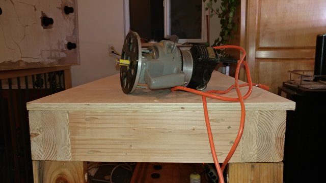
3/4 Maple ply glued with polyurethane glue and screwed. I had the sheet cut to 25" wide because the base it 24 1/8" wide to ensure there is support for the tank sides all the way around and there are some variations of about 1/16" in the width of the stand.
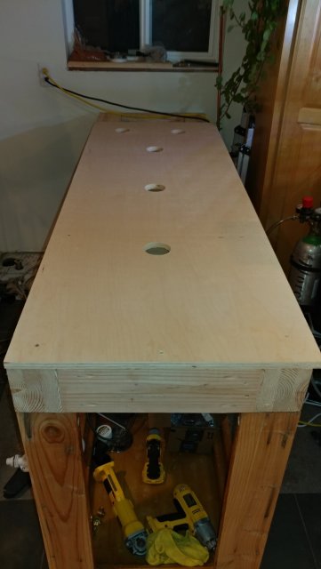
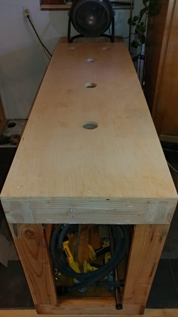
Here is the top mounted, flush cut for a perfect fit to the base with the first coat of water based Polyurethane on it. The white dots are screw holes with plenty of poly on them to keep them from rusting. I also put a couple of coats of poly on the underside of the top and the top base to seal it from humidity. The outside surfaces are not coated because I don't want to weaken the bond between the veneer and the base. Another 2 coats and I will put the tank on top, half fill the tank for weight, then fine tune the upper base to lower base fit to make sure everything is level.

3/4 Maple


Here is the top mounted, flush cut for a perfect fit to the base with the first coat of water based Polyurethane on it. The white dots are screw holes with plenty of poly on them to keep them from rusting. I also put a couple of coats of poly on the underside of the top and the top base to seal it from humidity. The outside surfaces are not coated because I don't want to weaken the bond between the veneer and the base. Another 2 coats and I will put the tank on top, half fill the tank for weight, then fine tune the upper base to lower base fit to make sure everything is level.
Last edited:

3 coats of water based poly in an hour and it will be dry by tomorrow without stinking up my house with off gassed solvents! I love working with water based polyurethane for these types of projects!
In case you are wondering water based polyurethane is actually tougher than oil based finishes. Water based poly leaves a very flat finish to the wood. It doesn't "POP" the character of the grain like the oil based finish on my stair case. Both the top and the staircase balusters are maple. The top is water based poly and the balusters are an oil based finish.
Once the poly dried and I put the tank on top of it I found the tank rocked. There is about 1/4" between the back left and the front right corners. So the front left and back right corners are high.  The thing is this is going to change when I get weight on it so I really need to tweak the tank to level with some water in it. This is what I came up with:
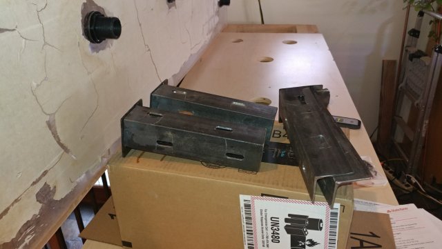
I spent most of the day cutting and welding them together. Once I get every thing tweaked perfectly I will put some shims between the top (ladder) and the corner posts so the weight rests on the shims instead of depending on the clamping force of the bolts on the brackets holding the corners up. The brackets will be there to keep everything together no really there to support the weight.
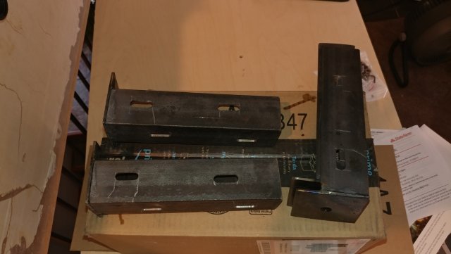
I figure I will level everything before I put the veneer on the stand so the veneer will cover up the adjustment gaps.

I spent most of the day cutting and welding them together. Once I get every thing tweaked perfectly I will put some shims between the top (ladder) and the corner posts so the weight rests on the shims instead of depending on the clamping force of the bolts on the brackets holding the corners up. The brackets will be there to keep everything together no really there to support the weight.

I figure I will level everything before I put the veneer on the stand so the veneer will cover up the adjustment gaps.
Last edited:


